Flux angle mapping magnetic gear
A coaxial magnetic gear for high gear ratios that needs much thinner back irons than the conventional design.
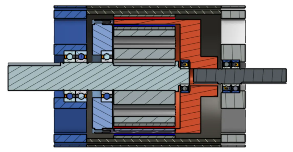
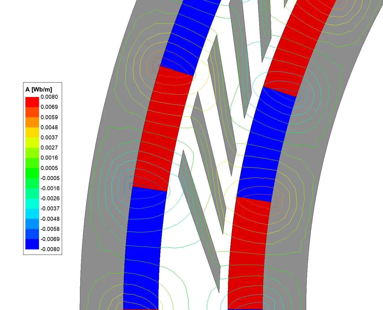
Flux angle mapping (FAM) is a magnetic gear technique for high gear ratios. Compared to a conventional coaxial magnetic gear, the magnets on the inner and outer rotor are much closer in size, which allows the back iron to be much thinner and the gear to be lighter overall. This project implements the technique in a prototype to validate the FEA results. If you are new to magnetic gears, this short background may help.
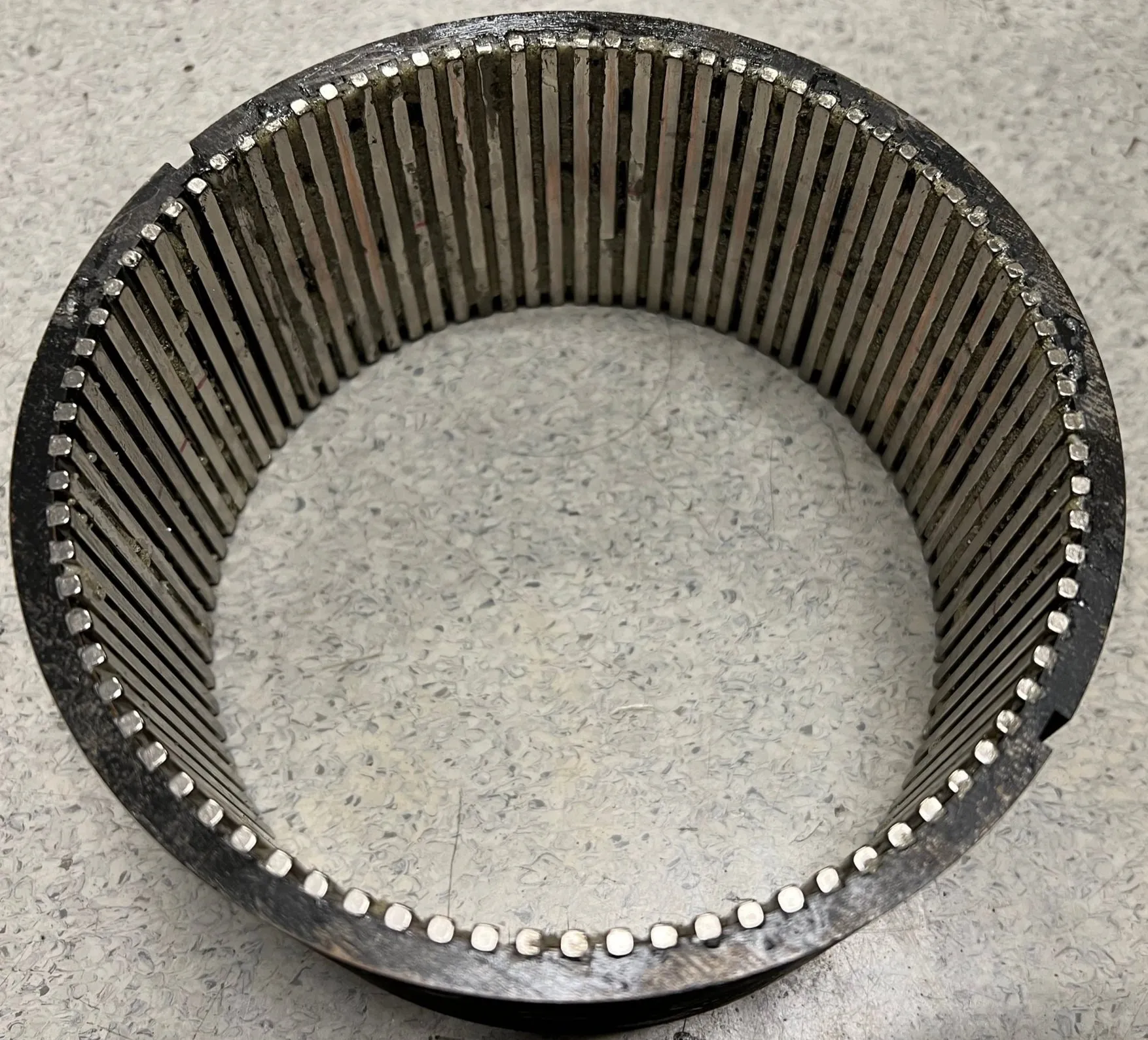
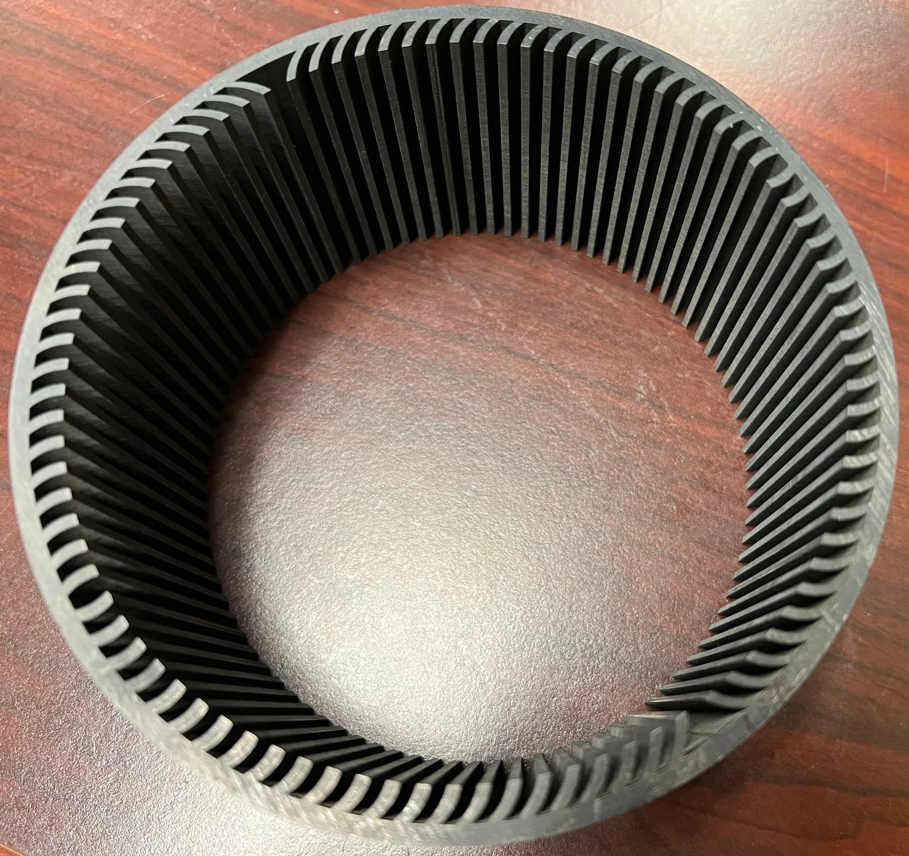
Fig. 1 and Fig. 2 show a conventional gear and a FAM gear with the same gear ratio of 20:1. Notice the significantly thinner back irons on the FAM design.
Work
- Built a detailed electromagnetic FEA model in Ansys Maxwell for design optimization and performance simulations
- Developed the mechanical design of the gear and iterated on it
- 3D printed the housing, support structures and other parts
The inner rotor, the outer stator and the ferromagnetic piece (FP) rotor are all made of hundreds of thin sheets of electrical silicon steel that are stacked and bonded together (laminations). This is done to reduce eddy current losses.
The outer bridge
The FP rotor consists of 91 flux angle “mappers”, each a different size and shape. To get the lamination stack manufactured, a thin bridge was added to the outside diameter to hold all the FPs together. The bridge made the laminations manufacturable, but it shorts out magnetic flux from the magnets and significantly decreases the maximum torque, so it has to be removed. That leaves the FPs to be suspended between the rotors, with a gap of only 1 mm on each side.
We considered three ways of holding them:
- Injection molding the whole FP rotor in plastic and then machining away the bridge. The initial cost was very high.
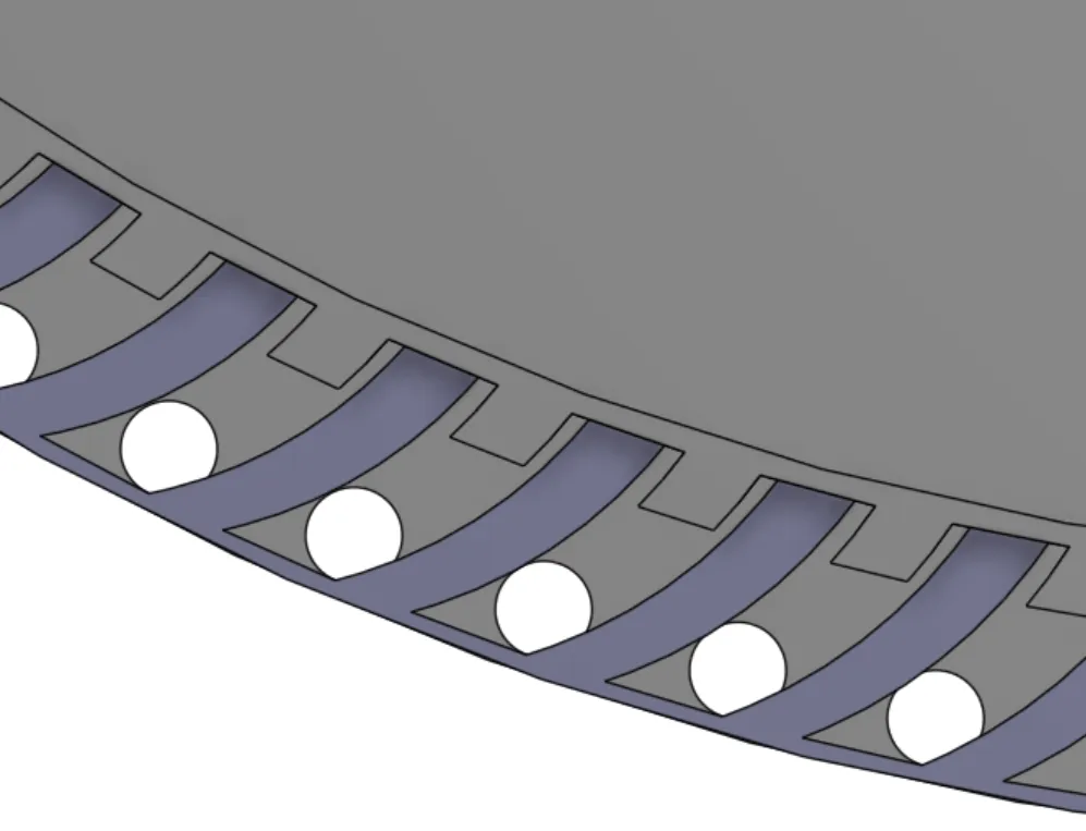
- 3D printed “fingers” that fill the negative space between the FPs (Fig. 8). The printed parts were not rigid enough, and getting an accurate press fit between the fingers and the FPs was difficult.
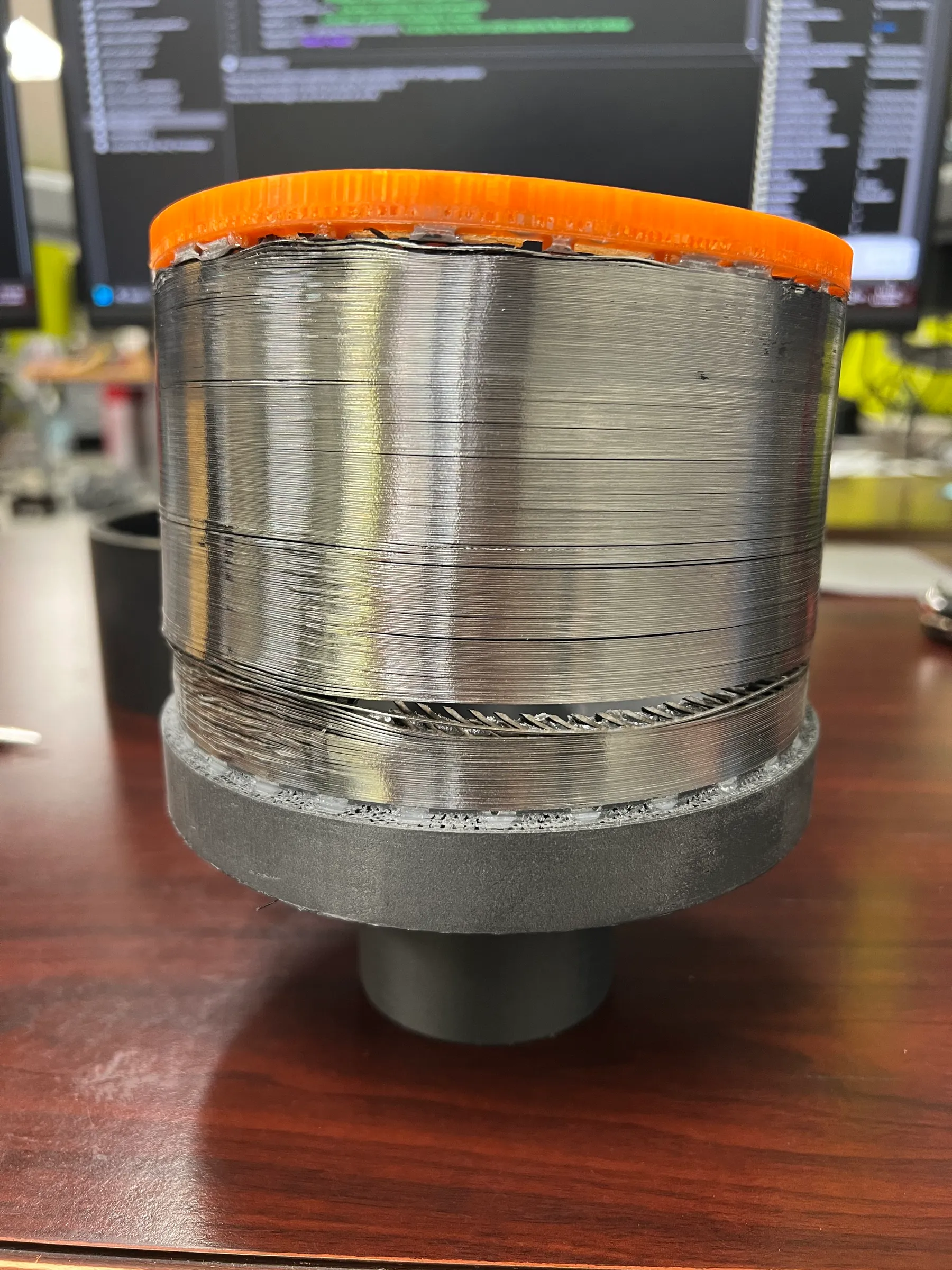
- Casting the whole FP rotor in epoxy resin and then machining the bridge away. This is the method shown in Fig. 3.
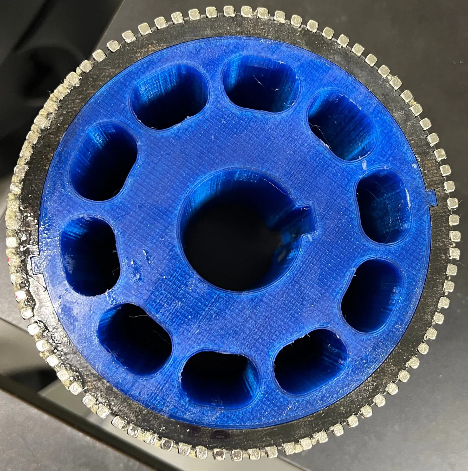
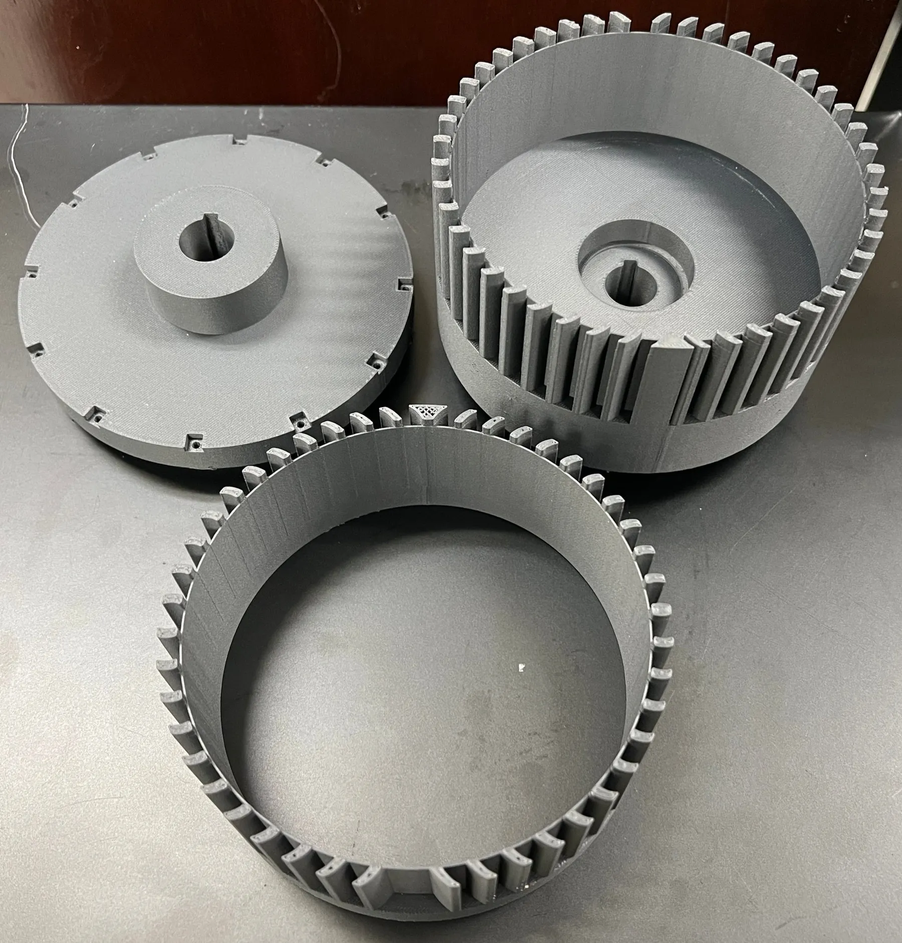
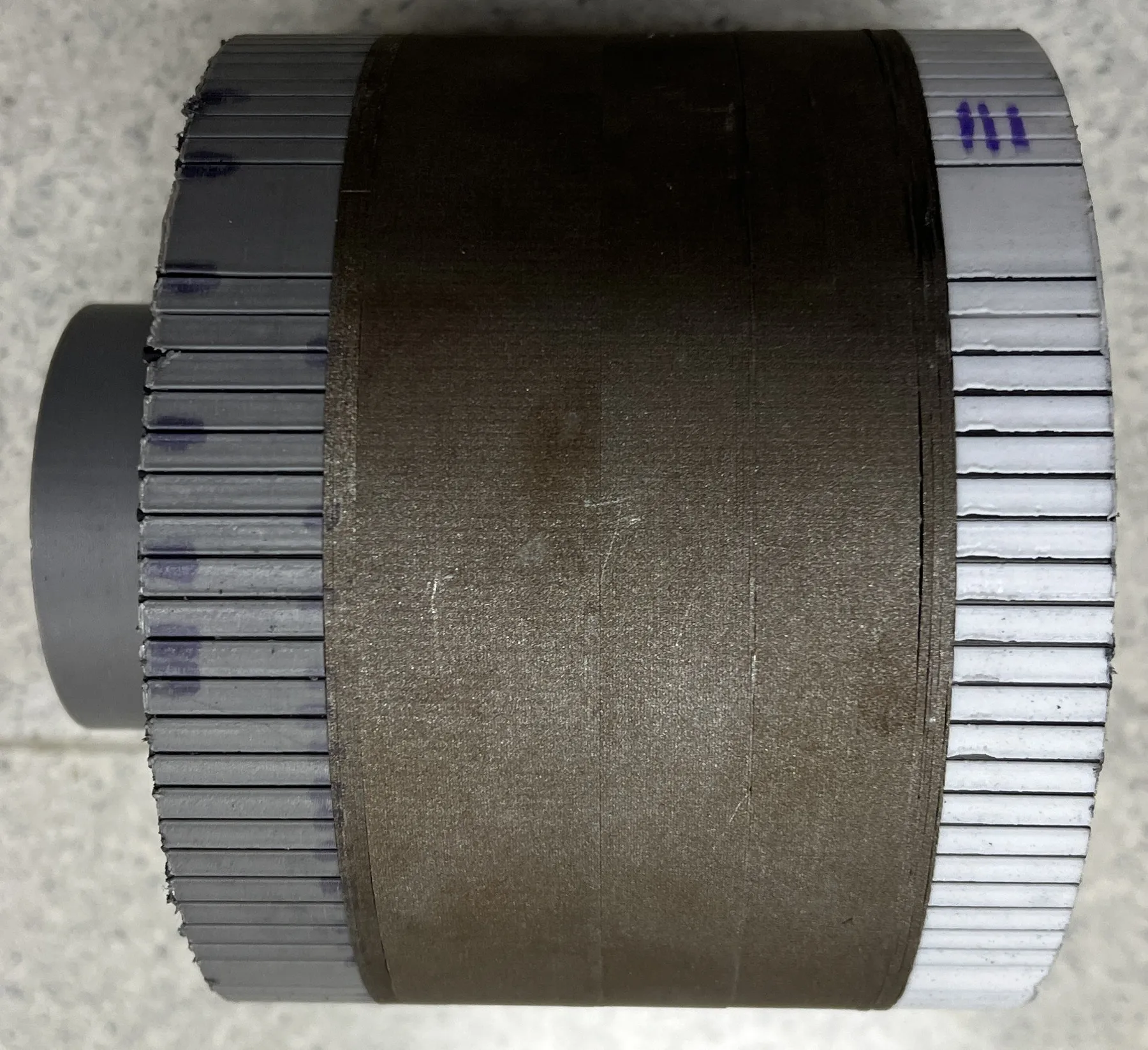
The first epoxy attempt failed on the last pass of machining, when the tool got slightly caught on a protrusion on the inner diameter (Fig. 9). After that, both air gaps were increased to 1.5 mm and several more designs were tested. The one that proved stiffest, while still being possible to assemble with the equipment in our lab, was a 3D printed PETG rotor with small nubs that fit between the FPs and carbon fiber rods placed as far outward as possible (Fig. 10 and Fig. 11). A thin 0.4 mm bridge was kept on the laminations, since individual lamination stacks for each FP would be extremely costly.
Results
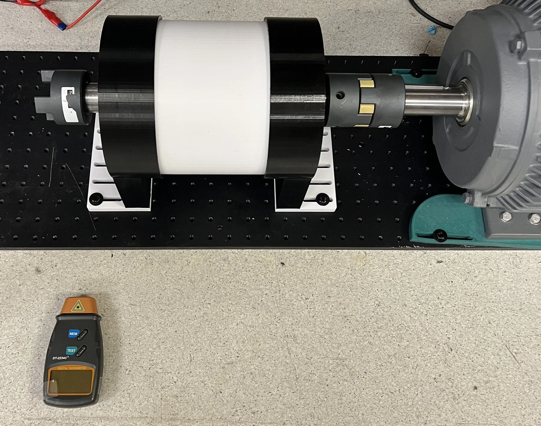
- The prototype was completed and tested (Fig. 12). It is the first FAM prototype reported in the literature
- The measured slip torque was 6.8 N·m, 6.1% lower than predicted by 3D FEA once the bridge and the larger air gaps are accounted for
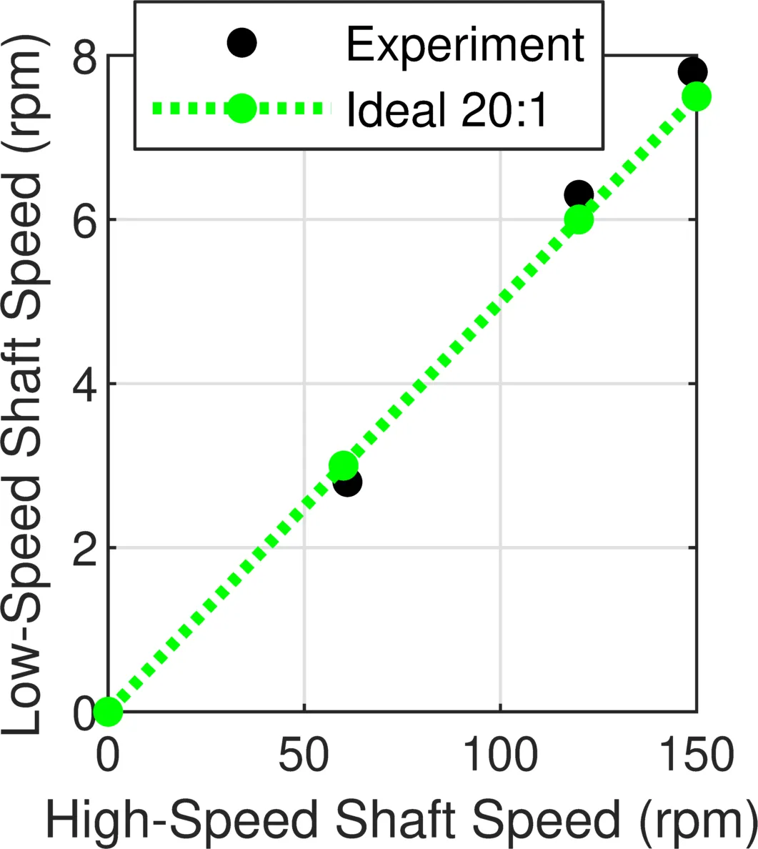
- The ratio of the shaft speeds agreed with the predicted 20:1 gear ratio (Fig. 13)
Limitations
After the prototype was spun by a motor to demonstrate the gear ratio, significant rubbing developed because one of the 3D printed parts failed, so the efficiency could not be measured. The prototype was also designed conservatively to keep it inexpensive, so it does not represent the torque density this topology can reach.
Papers
- Analysis of Bridge Placement and Ferromagnetic Piece Curvature on Performance of Coaxial and Flux Angle Mapping Magnetic GearsIEEE Trans. Ind. Appl., early accessIEEE XplorePDF
- Analysis of Bridge Placement and Ferromagnetic Piece Curvature on Performance of Coaxial and Flux Angle Mapping Magnetic GearsIEEE IEMDC, 2025IEEE XplorePDF
- Comparison between Flux Angle Mapping and Cycloidal Magnetic Gears for High Gear Ratio ApplicationsIEEE ECCE, 2024IEEE XplorePDF
- Flux Angle Mapping Coaxial Magnetic Gears for High Gear RatiosIEEE ECCE, 2022IEEE XplorePDF
Some figures on this page are from these papers. © IEEE.